PL Prod PARTNER Construction
By
Earl Haury
General
The Partner kit discussed is the “standard” kit with CF fuselage along with the NomexÒ honeycomb (nest of bee) firewall, formers, and floor. The procedures incorporated were chosen to accommodate equipment choices, provide a durable lightweight aircraft, and ensure accuracy. Some steps follow a logical order and others are builder’s choice. There are a number of photos to help clarify details. Rather than imbed them in this Word document, I’ve included them in a separate file and referenced them by filename. These may be view on your PC and / or printed as you chose. I suggest reading through the entire document before beginning construction, as some options may affect previous steps. Most hole sizes will be referred to by the numerical drill for the required size hole.
Equipment
My equipment choices include the YS140DZ engine, Hyde 140AR mount, AAP header, ES pipe, TT LBP Spinner, Tettra 20 oz tank, JR9411 elevator servos (2), Futaba 9150 aileron servos, JR8411 rudder servo, JR3421 throttle servo, Futaba 9Z XMTR & receiver, 1650 NiMH 5 cell battery, 5.7 volt regulator / perfect switch, 4-40 MK control hardware, H9 TT pushrods, Bolly CF wheel pants, MK tail wheel, Monokote & PPG finish. Finished weight is 10.25#. (Several ounces may be saved by using the lite Hyde mount, smaller servos, and 4 cell battery. Your choice.)
Composite Issues
The composite Partner fuselage is a combination of carbon, carbon overlaid with foam and fiberglass, KevlarÒ, and Kevlar overlaid with foam and fiberglass. Wash the composite parts with warm soapy (dishwashing soap works well) water to remove residuals from the epoxy cure and rinse well. Washing helps ensure good glue adhesion to the fuselage composites.
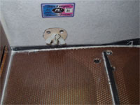
The exterior is an epoxy gelcoat; care should be exercised to not sand through the gelcoat to expose the composite material, especially in the areas constructed of Kevlar. On the other hand, the glass/foam should be removed where interior load bearing components will be mounted. (Wing tube biscuits, servo trays, wing adjusters, etc.) The fuse skin is quite flexible and is easily distorted by fitting interior components to tightly. Ensure that interior structure (bulkheads, trays, etc.) is a loose fit and carefully check for exterior distortion before gluing. SharpieÒ pens work well for marking on the gelcoat and marks are easily removed with a solvent such as CA debonder.
Cutting and / or drilling of the composite parts is best done with grinding stones, sanding drums, and cutoff wheels driven with a DremelÒ tool. Do not use steel burrs! (In addition to being hard to control, a burr can grab a Kevlar thread and rip it from the fuse!) It’s good practice to wear a dust mask when grinding or sanding composites, as carbon or Kevlar dust is likely injurious to the lungs.
Adhesives
Adhesives used are Loctite HysolÒ 9462, a slow cure thixotropic epoxy with exceptional bonding to the fuselage composite for high strength and/or fuel proof assemblies, and polyurethane (ProBondÒ or equivalent) for lightweight bonding. The Hysol epoxy is available, with a handy mixing applicator, from several sources (search for “Hysol” on RCU) or as AeropoxyÒ from BVM. Probond is available at local hardware stores. A caution, Hysol weighs 60 grams net per tube, use sparingly! CA is used for hinge assembly and 30 minute epoxy or Probond for most balsa assembly.
Fuselage Flange Trimming
The flanges of the fuse, canopy / hatch, and cowl require trimming to about 3/8-inch width. Do not cut the connecting composite of the fuse at the midpoint of the hatch opening, this is necessary to maintain width dimensional stability until the formers are installed. Begin by using a drawing compass or carpenters scribe, affixed with a Sharpie, and mark the flange widths to 3/8” from the exterior surface. Use a cutoff wheel and drum sander, then sanding block to remove material to the marks.
Canopy / Cowl
Install the canopy and cowl anchors next. It’s considerably easier to do this before the firewall and floor are installed. Your choice as to mounting, as several methods will work equally well.
I chose to use 2 – 1/8-inch diameter CF pins at the rear of each with 1/8” ID brass tubing for the sockets. Installation involves first gluing (Hysol) 1/8 inch ply plates to the backside of the flanges at each pin position. Drill the canopy / cowl side a little oversize, affix the canopy / cowl with tape, and mark the mating surface through the existing hole. Remove the canopy / cowl and drill the mating surface. Clean and roughen the glue surfaces of the brass tubes and carbon pins. Trial fit and adjust holes as necessary to ensure that the cowl / canopy is a good fit to the fuselage. Tape the cowl / canopy in place and glue the tubes / pins in place (Hysol) and allow to cure overnight.
The fasteners for the cowl / canopy are 4-40 socket head capscrews threaded into blind nuts. Placement on the canopy at about 6 inches rearward is OK. Location on the cowl must consider the exhaust header location and the minimal engine clearance at the cowl front. About 5 ½ inches forward on the left and 7 inches forward on the right works with the DZ.
At minimum, a 1/8” ply plate of ½” length under the flange at each screw location is needed. I chose to fit 3/8” poplar dowels into the canopy / cowl at each screw location. The dowels are prepared by cutting to 2 inches length, drill thru #33l, then bore ¼” for 1 3/8” (4 flute ¼” end mill best). The #33 hole is enlarged to #24 for 1/8 inch depth at the interior end. Thread four 4-40 blind nuts (DuBro) onto a capscrew, chuck in drill and rotate against a disc sander to reduce the blind nut head diameter to ¼ inch. Drill each blind nut #33, removing the threads. Press a modified blind nut into the relieved hole inside each dowel with a dab of epoxy. The modified blind nut provides a seat for the screw head and prevents its wearing into the wooden dowel over time.
Drill a #33 hole in the canopy / cowl flange at the hold-down bolt location. Fit the prepared dowel to this location so that the holes match and the dowel is perpendicular to the flange. Glue (Hysol) in place using a small reinforcement of 1.5 oz fiberglass cloth. When the epoxy has cured, drill #33 through the dowel and the canopy / cowl surface. Enlarge the hole in the surface with a grinding stone so as to accept the head of a 4-40 socket head capscrew. Mark the fuselage flange at the bolt locations and epoxy a 1/8-inch ply plate below the flange. Tape the cowl / canopy in place and drill through each dowel with a #33 size drill to place a matching hole in the fuselage flange / ply plate. Remove the canopy / cowl and enlarge the fuse flange holes to #24 and install 4-40 blind nuts with a small amount of epoxy. Install the canopy / cowl with 1” x 4-40 socket head capscrews, verify the fit and allow the epoxy to cure.
Engine, Mount, Firewall
Firewall / engine installation requires some considerations as they are interdependent.
I chose the Hyde AR mount
without the nose ring and not the lite model. My view is that the lite mount, by
using only the rear mounting screws, places more load on the nose ring which
must be more solid. A more solid nose ring transfers vibration to the fuse that
results in noise. Likewise, the ARI mount with integral nose ring places much
more load on the firewall. The latter will result in engine movement as the
firewall ages. 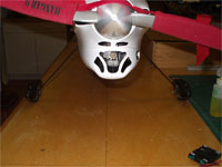 There is less room at the cowl front than in a Smaragd and
careful planning is necessary to ensure clearance. The pump / regulator assembly
of the 140 DZ will require removing more material than is ideal from the cowl to
provide clearance. (The 160 DZ pump / regulator is
closer to the crankshaft and may provide clearance problems at the cowl/ fuse
interface also.) Although I didn’t do this, my suggestion is to move the
engine back ¼ inch by using a ¼” spacer between the drive hub and spinner
backplate. (This may also allow moving the left cowl attachment bolt to the
front of the
exhaust pipe area.)
There is less room at the cowl front than in a Smaragd and
careful planning is necessary to ensure clearance. The pump / regulator assembly
of the 140 DZ will require removing more material than is ideal from the cowl to
provide clearance. (The 160 DZ pump / regulator is
closer to the crankshaft and may provide clearance problems at the cowl/ fuse
interface also.) Although I didn’t do this, my suggestion is to move the
engine back ¼ inch by using a ¼” spacer between the drive hub and spinner
backplate. (This may also allow moving the left cowl attachment bolt to the
front of the
exhaust pipe area.)
Mount the engine to the Hydemount. Some beam material will need to be removed to clear the crankcase “belt” on the 140/160 YS engines. Leave some clearance between the rear of the engine and mount to allow for a header brace (and DZ injector supply fuel fitting if using an L for fitting). I drill the mount beams #24 and press heated 4-40 blind nuts (DuBro only) into the beams with a little epoxy to fasten. The engine is mounted with 4-40 socket head capscrews and washers. I also chose to use 4-40 capscrews to fasten the Hydemount to the firewall, rather than the recommended 6-32 size. This requires reducing the OD of four #4 washers (place on bolt and turn with drill against sanding disc) to fit into Hydemount bolt recesses.
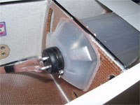
Fabricate a 1/16 inch ply “washer” with an ID larger than the engine drive hub and an OD that matches the spinner (3 3/8” Tru-Turn PL should be available, otherwise a 3 ¼” will suffice). Spot glue the washer to the spinner backplate. This will set the spinner / fuse clearance during installation. Open the nose of the fuse to a 3/8” flange as was done with the canopy / cowl openings and ensure the surface is flat with no protrusions at the seam.
Install the engine and mount by hanging from the spinner with ply washer installed. (Don’t forget the ¼ drive space between the hub and spinner if using.) Center and tape the spinner to the fuse. Align engine vertically and tape in place. Carefully trim the CF honeycomb firewall to fit the fuse and against engine mount. (Be careful of tight spots that will distort the fuse exterior.) Apply double sided tape, or spots of glue, to the firewall in the area of the engine mount. Affix the fitted firewall to the mount and carefully unbolt engine. Withdraw the firewall and mount. Mark location of the mount with an index mark, and location of mounting screw holes. Also mark the location of fuel line opening and throttle pushrod. (Consider location of fuse floor and ensure that the locations are above the floor.)
Remove the mount from the firewall. Bore the firewall at the mounting bolt locations with a sharpened ½- inch OD brass tube. Epoxy (Hysol) short pieces of 1/2” diameter hardwood dowel into the firewall. Cut the dowels flush with the firewall (a Dremel router set flush works well). Likewise bore the fuel line / pushrod locations for dowels install lighter poplar dowels, drill for pushrod / fuel line, bevel fuel line hole to remove sharp edges and harden dowels with thin CA.
Carefully reestablish the
mount bolt locations and drill dowels #33. Construct a 3” OD by 1 ½” ID
disc of 3/32” 5-ply plywood and drill 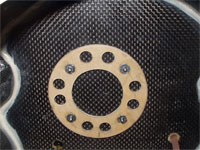 #25 at the mount bolt pattern locations.
Lighten by cutting eight 3/8” holes (tubing drill) equally spaced between bolt
locations. Install 4-40 blind nuts (DuBro only). Relieve the rear of the holes
in the firewall dowels #25 X 1/8” for blind nut clearance. Install mount to
firewall with 4-40 socket head capscrews and blind nut ring. Spot glue ring to
firewall.
#25 at the mount bolt pattern locations.
Lighten by cutting eight 3/8” holes (tubing drill) equally spaced between bolt
locations. Install 4-40 blind nuts (DuBro only). Relieve the rear of the holes
in the firewall dowels #25 X 1/8” for blind nut clearance. Install mount to
firewall with 4-40 socket head capscrews and blind nut ring. Spot glue ring to
firewall.
Re-install the engine into the fuse with spinner and spacer. Install the firewall with mount attached. Bolt engine to mount and double check alignment at nose, and firewall fit. With spinner taped to fuse to maintain center position, stand the fuse on its nose and glue the firewall in place with a bead of Hysol on the rear side. Allow to cure overnight.
Nose Ring
Fabricate a nose ring mount
by cutting a 4 inch diameter OD (slightly larger if engine is moved back as
suggested) disc from 1/8” bi-directi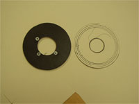 onal carbon fiber / end grain balsa (CF/EGB)
with an 1 ¼” center hole (apply masking tape to
both sides before cutting or drilling).
Verify the fit in the fuse nose with engine mounted. Bevel the disc to
fit fuse and adjust it to ensure nose ring will fit the front third of the
engine bearing boss. Using a CF Engineering aluminum / O-ring nose ring on the
engine, mark the fastener holes in on the CF mount in horizontal plane. Rotate
the nose ring 90 degrees and mark for another fastener hole at the top to
accommodate a 3 point mounted custom nose-ring (detailed later). Drill hole
onal carbon fiber / end grain balsa (CF/EGB)
with an 1 ¼” center hole (apply masking tape to
both sides before cutting or drilling).
Verify the fit in the fuse nose with engine mounted. Bevel the disc to
fit fuse and adjust it to ensure nose ring will fit the front third of the
engine bearing boss. Using a CF Engineering aluminum / O-ring nose ring on the
engine, mark the fastener holes in on the CF mount in horizontal plane. Rotate
the nose ring 90 degrees and mark for another fastener hole at the top to
accommodate a 3 point mounted custom nose-ring (detailed later). Drill hole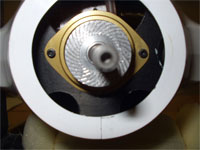 locations #25 and install blind nuts with epoxy. Open
the center ID to 1 9/16”, lighten disc by removing bottom, and opening to
clear airscoop inlets. Install the engine and
nose ring components with the CF plate 5/8” rear of nose (engine stock
location, 7/8” engine ¼” rear). Install the spinner and verify alignment,
glue (Hysol) nose ring mount to fuse and allow overnight cure.
Remove the nose ring, engine, and mount. Epoxy
(Hysol) front
of firewall to fuse.
locations #25 and install blind nuts with epoxy. Open
the center ID to 1 9/16”, lighten disc by removing bottom, and opening to
clear airscoop inlets. Install the engine and
nose ring components with the CF plate 5/8” rear of nose (engine stock
location, 7/8” engine ¼” rear). Install the spinner and verify alignment,
glue (Hysol) nose ring mount to fuse and allow overnight cure.
Remove the nose ring, engine, and mount. Epoxy
(Hysol) front
of firewall to fuse.
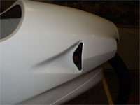
Exhaust System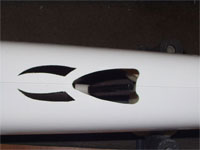
Re-install the
mount & engine. Assemble the exhaust system into the fuse with the stinger
up and determine rear exit location (be sure to do this before installing the
fuse floor). Mark and cut rear exit location. This  location is Kevlar composite, work carefully with a cutoff wheel and grinding
stones. CA the edges and sand to remove “fuzzies”. Open the pipe tunnel
entrance behind firewall, leaving only a narrow fuse cross piece at firewall.
location is Kevlar composite, work carefully with a cutoff wheel and grinding
stones. CA the edges and sand to remove “fuzzies”. Open the pipe tunnel
entrance behind firewall, leaving only a narrow fuse cross piece at firewall.
Landing Gear (Main)
The landing gear mount material offers some options. The plywood mount supplied is adequate, but a bit heavy. I chose to fabricate a reinforced 1/8” CF/EGB mount. Due to the width of the mount, the landing gear loads tend to flex the center of the mount downward. This not only is unwanted flexing of the mount, but also puts a bending load on the fuse sides at the mounting point. To prevent this I placed a CF “beam” vertically at the center top of the mount.
The only clue to the intended gear location is the CF reinforcement in the fuse. I chose to install the mount / gear centered in the CF reinforced area, 5 inches below the canopy flange. It’s important to install the mount parallel to the fuse centerline to avoid an odd gear angle. The end result is a gear that “looks right”, has a good deal of weight on the tail wheel for good grass field performance, and works perfect in both takeoff tracking and landing.
Roughly fit the
stock ply mount to the fuse (or make a template) and copy to the 1/8” CF/EGB
material (apply masking tape to both sides before cutting or drilling).
Carefully fit the mount to the fuse, centered in the CF reinforced area, 5
inches below the canopy flange. Block the fuse so that the fin centerline is
vertical (insert the rudder post without glue, tape the fuse / post together,
and mark centerline on post). Ensure that the mount is perpendicular to the fin
CL. Likewise, ensure that the mount is parallel to the wing centerline (canopy
flange). A small bubble level on the gear mount is handy for this alignment.
Mark the fuse and remove the mount.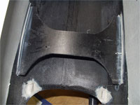
Cut the land ing
gear into two equal halves. Drill three #24 holes in the mounting flange of each
leg. (2 located 3/8” from front edge, 1 located 5/16” from rear edge,
equally spaced on flange.) Install 4-40 (DuBro) blind nuts with epoxy in each
hole from the bottom of each flange. Clamp the landing gear to the mount,
ensuring front / back centering and parallel to center. Place top flange / leg
juncture inside mount end 1/16”. Mark mounting holes and drill mount
#32. Attach the gear with 4-40 x ½” capscrews and washers, then
recheck alignment.
Remove the gear and
harden the mount holes with CA and re-drill, seal edges of mount with CA.
Install the landing gear mount with Hysol (no epoxy on top mount to fuse edge
now) and fillet on bottom. Double check alignment and allow to cure.
ing
gear into two equal halves. Drill three #24 holes in the mounting flange of each
leg. (2 located 3/8” from front edge, 1 located 5/16” from rear edge,
equally spaced on flange.) Install 4-40 (DuBro) blind nuts with epoxy in each
hole from the bottom of each flange. Clamp the landing gear to the mount,
ensuring front / back centering and parallel to center. Place top flange / leg
juncture inside mount end 1/16”. Mark mounting holes and drill mount
#32. Attach the gear with 4-40 x ½” capscrews and washers, then
recheck alignment.
Remove the gear and
harden the mount holes with CA and re-drill, seal edges of mount with CA.
Install the landing gear mount with Hysol (no epoxy on top mount to fuse edge
now) and fillet on bottom. Double check alignment and allow to cure.
Fuselage Floor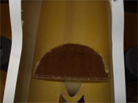
The fuse floor panel needs only a little trimming to fit, mostly to accommodate the firewall position. Cut the fuse cross piece with a scissors to permit insertion of the floor, but do not remove. Applying the floor onto the landing gear mount adds strength to that installation. In order to accomplish this, as it raises the rear of the floor slightly, I trimmed 1/8” from the bottom of the “tank” bulkheads. With the floor fit and positioned, determine the location of the rear pipe tunnel bulkhead. Fit this bulkhead and glue (Hysol) to the fuse (only) using the floor to establish its height. Mark the floor at the center of the landing gear mount and at the landing gear mounting bolt locations. Bore 5/16” holes at the bolt locations to allow the mounting capscrews with washers to fit against the mount. Cut a 1/8” X 6” slot in the floor on the LG centerline.
Prepare the LG load beam from 1/8” solid CF material (Aerospace Composites). The beam is 6” long by ½” high, with the outer 1 ½” tapered to ¼” high. This part weighs ½ ounce and could be lightened without compromising strength by drilling some equally spaced holes, say 3/16” diameter.
Roughen and clean the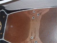 top
surface of the LG mount and the bottom edge of the load beam. Apply Hysol to the
LG mount, top edge at fus
top
surface of the LG mount and the bottom edge of the load beam. Apply Hysol to the
LG mount, top edge at fus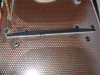 e, and top edge of the rear pipe tunnel bulkhead. Apply
Probond to the floor at the fuse interface behind the tank bulkhead. Install the
fuse floor and temporarily position the tank bulkheads. Apply Hysol to the floor
/ fuse / firewall interface in front of the tank bulkheads. Apply a liberal
amount of Hysol into the slot for the LG mount beam and install the beam, remove
excess epoxy. Weight the floor / beam to the LG mount and rear pipe tunnel
bulkhead. Remove excess Probond foam as it cures.
Hysol the bottom floor / fuse / firewall interface after top
adhesive has cured.
e, and top edge of the rear pipe tunnel bulkhead. Apply
Probond to the floor at the fuse interface behind the tank bulkhead. Install the
fuse floor and temporarily position the tank bulkheads. Apply Hysol to the floor
/ fuse / firewall interface in front of the tank bulkheads. Apply a liberal
amount of Hysol into the slot for the LG mount beam and install the beam, remove
excess epoxy. Weight the floor / beam to the LG mount and rear pipe tunnel
bulkhead. Remove excess Probond foam as it cures.
Hysol the bottom floor / fuse / firewall interface after top
adhesive has cured.
Pipe Mounts
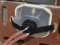
I prefer to mount the pipe at the front neck and stinger using wire ties and LordÒ mounts. I also prefer TeflonÒ connector of 8 inches or so between the pipe and header. A header brace, fabricated to fit the DZ / L YS mount bosses, and either an AAP or CD header provides a reliable system. The Partner cowl opening limits the Teflon tubing length to 5” or so to keep the front wire tie accessible. (I’m concerned about tubing life with this length.) A short piece of the appropriate size silicone tubing is placed over the pipe at the wire tie locations to insulate the tie from heat and protect the pipe from the Lord mount. A small metal clip is attached to the Lord mount with a flat head screw to finish the wire tie attachment.
The wire tie “ho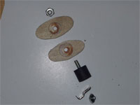 oks”
for the Lord mount are fabricated f
oks”
for the Lord mount are fabricated f rom thin SS about ¼” wide and long enough
to protrude past the Lord mount and acc
rom thin SS about ¼” wide and long enough
to protrude past the Lord mount and acc ommodate
the wire tie, with a 1/8” lip
bent to capture the wire tie. A hole for a flat head screw finishes the clip.
Fabricate two 1/16” ply oval plates, 1 ¾” x 7/8” to reinforce the
front attachment point. Center drill both plates #19. Determine the mount
location, drill the floor #19, epoxy floor plates to each side of floor and
secure with #8 screw of ½” x ½ “ Lord mount and 8-32 aluminum nut.
ommodate
the wire tie, with a 1/8” lip
bent to capture the wire tie. A hole for a flat head screw finishes the clip.
Fabricate two 1/16” ply oval plates, 1 ¾” x 7/8” to reinforce the
front attachment point. Center drill both plates #19. Determine the mount
location, drill the floor #19, epoxy floor plates to each side of floor and
secure with #8 screw of ½” x ½ “ Lord mount and 8-32 aluminum nut. 
 The rear pipe
mount is spaced down from the floor by two pieces of ¼” Carbon / Nomex
honeycomb. Fab one piece 5/8” x 7/8” and center drill #19 and another 1
1/8” x 7/8” and center drill ½”. Hysol the CF pieces together,
maintaining hole centers, then Hysol to the bottom of floor at rear mount
location under pipe stinger, large hole toward floor. Allow to cure. Open hole
in floor to match ½” hole in mount, install Lord mount with 8-32 aluminum nut
in floor hole and wire tie clip on bottom.
The rear pipe
mount is spaced down from the floor by two pieces of ¼” Carbon / Nomex
honeycomb. Fab one piece 5/8” x 7/8” and center drill #19 and another 1
1/8” x 7/8” and center drill ½”. Hysol the CF pieces together,
maintaining hole centers, then Hysol to the bottom of floor at rear mount
location under pipe stinger, large hole toward floor. Allow to cure. Open hole
in floor to match ½” hole in mount, install Lord mount with 8-32 aluminum nut
in floor hole and wire tie clip on bottom.
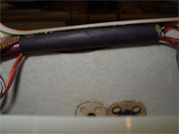
Insulate ES pipe neck with ¾” ID x 1” and stinger with 3/8” ID x 1” silicone tubing. Install the pipe assembly and secure with wire ties. Check for adequate clearance and alignment. Determine dimensions of header brace, fabricate from SS, and install.
 |
|
 |
 |
Tank Bulkheads
Remove the tank bulkheads
and mark for tank cutouts. The provided pattern outlines the use of two MK
tanks, as MK does not offer a large tank. I chose to use the Tettra 20 ounce
tank and mount it centered in the fuse. Prepare a template of the tank cross
section and mark the bulkheads at 2” above bottom for the front and 1 3/16”
above bottom for the rear. Cut lightening holes pretty much like provided
patterns, adding a hole in each at the bottom left is useful for routing the
throttle servo lead. As the tank opening is very close to the top of the
bulkheads, I routed (4 Dremel cutoff wheels sandwiched) the Nomex material from
between the glass 1/8” deep at each bulkhead top and glued (Hysol) a 1/8” CF
tube across the top of each bulkhead.
Fit the front bulkhead 2” ahead of the wing tube center and the other 3 1/8” behind the wing tube center. Again, ensure no tight spots that deform the fuse exterior and Hysol into place. Let cure overnight. Epoxy or CA the fuse “connector” that was cut to install the floor together with a piece of 3-ounce glass cloth on the bottom. (Primarily to ensure proper fuse width at bulkheads.)
Alignment
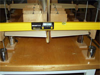
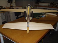
I use a fuselage jig to hold the fuse during alignment along with “Vee” blocks on stands to support and position the wing / stab panels. Most alignment measurements are then performed using a 48” digital level, which provides 0.1-degree accuracy. There are other ways to achieve the same results, however the effort required to build the jig and Vee blocks is relatively low considering that they will ensure accuracy and make future building easier. The fuse jig is of my own construction and is typical of available fuse jigs but sized for 2-meter fuselages. The Vee blocks are base on a K-Factor construction article by Eric Hawkinson.
With the fuse in the jig and the fin centerline again vertical, check the wing tube marks on each side of the fuse to ensure that they are of equal height. Ideally the fuse canopy flange is perpendicular to the fin centerline and parallel to the wing center reference dots, fore and aft of the wing, on the fuse. Shim the tail post to achieve a level wing centerline. If there are slight differences side to side with the fin vertical it’s necessary to split the difference between each side.
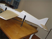
Wing Tube
Cut a 1
1/16-inch diameter hole in each fuse side centered on the tube marks (Ref PL
instructions). Fabricate 1/16” ply x 1”ID x 2”OD wing socket “biscuits”. Fit the wing tube socket in the fuse with biscuits and mark the
location of the biscuits. Carefully cut through the internal fiberglass and
remove the glass and foam where the biscuits will reside. Place the wing tube
socket, with biscuits, in the fuse and install the wing tube. Tape ½” sq.
spacers to each side of the fuse near the wing tube to space the wing panels
away from the fuse slightly (for excess socket length clearance). Slip the wing
panels into place against the spacers (the wings are as received at this point).
Tape 1/8” x 1” x1” lite ply protectors to the top and bottom of each wing
LE & TE at about mid-span. The LE – TE locations should be parallel to the
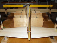
fuse centerline. Install the Vee blocks and adjust their stands so that the wing
panel centerlines roughly align with the fuse reference dots.
“biscuits”. Fit the wing tube socket in the fuse with biscuits and mark the
location of the biscuits. Carefully cut through the internal fiberglass and
remove the glass and foam where the biscuits will reside. Place the wing tube
socket, with biscuits, in the fuse and install the wing tube. Tape ½” sq.
spacers to each side of the fuse near the wing tube to space the wing panels
away from the fuse slightly (for excess socket length clearance). Slip the wing
panels into place against the spacers (the wings are as received at this point).
Tape 1/8” x 1” x1” lite ply protectors to the top and bottom of each wing
LE & TE at about mid-span. The LE – TE locations should be parallel to the
fuse centerline. Install the Vee blocks and adjust their stands so that the wing
panel centerlines roughly align with the fuse reference dots.
 Using the
digital level supported on the Vee blocks, adjust the Vee block stands so that
th
Using the
digital level supported on the Vee blocks, adjust the Vee block stands so that
th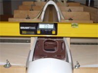 e level reads 0 degrees (incidence) for both wing panels.
Place the level span wise over the LE Vee blocks and adjust
to 0 degrees. Repeat for the TE.
Trammel the wing using a sufficiently long piece of 1/8 “ x 1” aluminum.
Attain the exact same distance from the fin post center to the wing TE tip.
Ensure that the wing tube fuse socket “floats” in the fuse and extends from
the fuse an equal amount on each side. Double-check all measurements and spot
glue the fuse socket with a couple of drops of thick CA. Release any support
pressure at the Vee blocks. Check fuse position in jig. Reset Vee blocks to meet
the natural position of wing panels. Repeat
i
e level reads 0 degrees (incidence) for both wing panels.
Place the level span wise over the LE Vee blocks and adjust
to 0 degrees. Repeat for the TE.
Trammel the wing using a sufficiently long piece of 1/8 “ x 1” aluminum.
Attain the exact same distance from the fin post center to the wing TE tip.
Ensure that the wing tube fuse socket “floats” in the fuse and extends from
the fuse an equal amount on each side. Double-check all measurements and spot
glue the fuse socket with a couple of drops of thick CA. Release any support
pressure at the Vee blocks. Check fuse position in jig. Reset Vee blocks to meet
the natural position of wing panels. Repeat
i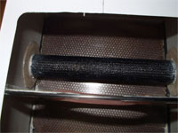 ncidence, span wise
perpendicularity, and fore – aft perpendicularity measurements. When satisfied
that they are correct, apply epoxy (Hysol) to wing tube socket inside fuse and
both biscuits. Slide the biscuits against fuse sides and let epoxy cure
overnight.
Mark wing centerline at LE – TE onto fuse. Check alignment
again when epoxy cures and leave assembly in jig.
ncidence, span wise
perpendicularity, and fore – aft perpendicularity measurements. When satisfied
that they are correct, apply epoxy (Hysol) to wing tube socket inside fuse and
both biscuits. Slide the biscuits against fuse sides and let epoxy cure
overnight.
Mark wing centerline at LE – TE onto fuse. Check alignment
again when epoxy cures and leave assembly in jig.
Stab Tube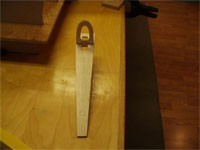

Cut stab tube holes as marked on the fuse to 7/16” diameter. Remove the fiberglass / foam where the stab plate fits in the fuse. Fit the rear bulkhead and balsa stab plate (plate fits below stab tube holes). Install the bulkhead / plate assembly with Probond on the bulkhead and Hysol on the plate edges.
To ensure a
solid stab mounting I chose to glue a CF stab tube permanently in place. The
process is the same if one wishes to have a removable tube, just use the socket
material in the fuselage.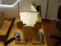
Remove a 1-inch square area of FG/foam above the stab plate at the stab tube hole. Cut two 1/8” x 1” sq. lite ply plates to fit the area of removed foam. Mark the stab tube hole on the plates and cut out accordingly. (If making the tube removable, open the plates so as to fit the stab tube socket material and cut the socket to fit inside the fuse sides.) Place the plates into the fuse and install the stab tube. Lightly clamp the tube to the stab plate. Fit the stab panels and support with Vee blocks positioned at the tips.
As with the wing, adjust the stab incidence and horizontal perpendicularity to 0 degrees. Trammel with the aluminum bar to ensure stab fore – aft alignment with wing. The distance from the trailing edge of the wing to leading edge of the stab at stab span should be the same on both sides. When satisfied, remove the tube clamp and check for any binding or twisting of the fuse and correct as necessary. Apply epoxy (Hysol) between the tube and stab plate, lightly clamp and re-check all alignment items. Let cure overnight.
|
|
 |
 |
 Reset the stab
Vee blocks and again check alignment. When satisfied, epoxy the lite ply plates
to the stab tube and fuse sides. Mix Hysol with micro-balloons to a light mix
and fillet the tube to the stab plate. Apply a light coat of Hysol over the
socket, saturate a strip of CF (5 oz.) cloth with Hysol and place over the
socket and about an inch fore –aft of the socket. Work any air from the cloth
to ensure saturation and adhesion. A little heat from a heat gun will assist
this process. Allow to cure overnight.
Reset the stab
Vee blocks and again check alignment. When satisfied, epoxy the lite ply plates
to the stab tube and fuse sides. Mix Hysol with micro-balloons to a light mix
and fillet the tube to the stab plate. Apply a light coat of Hysol over the
socket, saturate a strip of CF (5 oz.) cloth with Hysol and place over the
socket and about an inch fore –aft of the socket. Work any air from the cloth
to ensure saturation and adhesion. A little heat from a heat gun will assist
this process. Allow to cure overnight.
Stab Root Ribs & Adjusters
Begin constructing the stab root ribs by substituting 3/16” balsa for the supplied material. (The slight extra thickness makes fitting to the fuse easier and provides clearance for the adjuster mounting screw heads.) Draw a centerline on both plates and mark the tube and pin locations, basis marks on fuse. Cut (1/2” brass tube) tube socket hole. Position an adjuster at the pin location and mark the adjuster outline on the root rib. Cut the root rib on marks to accept adjuster. Cut 0.007" bi-directional CF composite to the root outline inside of the stab skins. Epoxy (30 min.) CF to inside of root rib, matching centerlines. Weight flat and allow epoxy to cure.
Place an
adjuster in the root rib cutout (flat side in) and drill the CF #46 at the
adjuster mounting screw points. Center drill #46 four 3/32” x 3/16” x 1” 5
ply strips. Apply 30-min. epoxy and affix a strip fore – aft of each adjuster
on the CF side of the root rib using #2 x 3/8” sheet metal screws through the
adjuster and CF. Allow to cure. Ensure that the adjuster openings on each rib
match with the ribs positioned on a stab socket section.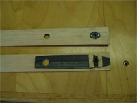
Remove the adjusters and trim the ply strips to fit inside the stab skins. Remove CF sufficiently to allow the setscrew side of the adjusters to fit between ply strips. Install the adjusters with epoxy (Hysol) and #2 sheet metal screws with the flat side of adjuster and screw heads toward fuse side of root ribs.
Place the stab root plates on stab tube with a tube socket bushing. Align the centerline with the reference dot on the fuse and tape in place. Mark the pin location at the center of the adjuster opening on each side. Remove the root ribs and bore a 1/8” hole where marked on the fuse. Verify pin alignment with adjusters and parallel to stab tube (2 planes). Remove the pin and remove glass / foam from around the pin hole inside fuse. Saturate a 1 ½” square CF cloth (5 oz.) with epoxy (Hysol) and glue to the stab plate, centered at pin location. Insert the pin, install stab panels and Vee block supports. Adjust stabs to 0 degrees incidence. Apply Hysol / micro- balloons liberally around pin. Saturate a 1 ½” x 2” CF cloth with Hysol and place over pin, warm with heat gun and work out any air bubbles. Double check alignment and allow to cure. Remove wing / stab panels and fuse from alignment jig.
Remove sufficient foam from the stab roots to accept the adjusters and mounts, as well as the CF reinforcement. Probond root ribs to stab panels taking care to maintain centerline alignment. Allow to cure.
Place 2“ wide
masking tape on the stab skin to prevent damage. Trim the stab root ribs to the
stab airfoil with 80 grit sandpaper. Trim the stab socket flush with the root
rib. Install the stab panels and match the root ribs to the fuse by working 220
grit sandpaper between the fuse / stab.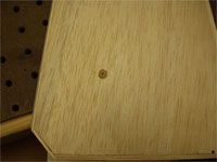
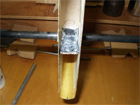
Locate the stab socket center 70mm from root. Carefully bore a ¼” hole to (not thru) stab socket using sharpened brass tubing. Center drill two ¼” x 3/8” pieces of poplar dowel #43 and glue (Probond) into the stab holes. Cut / sand the dowels flush with the stab skin. Install the stab panels and, while held tightly against fuse, drill through the stab socket and tube #43 using the dowel hole as a guide. Tap the dowel and tube 4-40. Bevel the dowel hole 60 degrees to provide flush installation of a 4-40 x ½” flat head screw.
Remove the stab panels and carefully cut holes in the skin with very sharp 3/32” brass tubing for access to the adjustment screws. Remove the wing panels.
Elevator Linkage Consideration
The forward position of the elevator hinge line relative to the rudder hinge line results in quite distant (from centerline) placement of elevator horns. This wide placement of the horns prevents any reasonable approach angle for in the fuselage elevator linkages, including cables. The most feasible approach is to use a small servo in each stab panel to provide accurate linkage alignment and force transfer. The stab airfoil is sufficiently thick that medium servos such as the JR9411 or Futaba 9550 may be installed flush with only the linkage exposed. CG effect with these servos is fine with a YS engine. Smaller servos (JR 3421) may be used to save weight and offset a lighter engine.
Rear Fuse Support (Ladder)
In order to minimize noise and improve compressive strength in the yaw plane, I chose to install a rear fuselage horizontal bulkhead or “ladder”.
First install
an antenna tube of “Nyrod” outer tubing through the fuse floor, behind the
pipe tunnel bulkhead, along the fuse bottom, and through the rear bulkhead,
extending to the tail post. Secure the tube with some small dabs of Probond.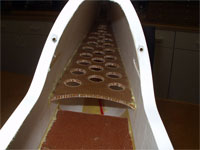
 Cut a 21”
long piece of 1/8” Nomex / glass honeycomb to 5” width at front and 2 ½”
width at rear. Work from a centerline so that the ends and Nomex matrix are
perpendicular to the fuse centerline. Remove excess material with 1” and ¾”
Forstner drill bits. Fit with the rear resting against the rear bulkhead and on
top of the stab plate and the front 2” above fuse (pipe) floor. Spot glue (Probond)
a Gator Featherlite servo lead tube down the middle of the “ladder”
extending rearward beyond the rear bulkhead. Again ensure no tight spots that
distort the fuse and glue the honeycomb ladder in place (Probond).
Cut a 21”
long piece of 1/8” Nomex / glass honeycomb to 5” width at front and 2 ½”
width at rear. Work from a centerline so that the ends and Nomex matrix are
perpendicular to the fuse centerline. Remove excess material with 1” and ¾”
Forstner drill bits. Fit with the rear resting against the rear bulkhead and on
top of the stab plate and the front 2” above fuse (pipe) floor. Spot glue (Probond)
a Gator Featherlite servo lead tube down the middle of the “ladder”
extending rearward beyond the rear bulkhead. Again ensure no tight spots that
distort the fuse and glue the honeycomb ladder in place (Probond).
Wing Adjusters
Center drill the wing adjuster plates using 7/32” brass tubing. Center the pin of an adjuster, insert the pin through the plate hole, align the width of the plate with the bolt holes and mark the holes. Drill the plate #36. Draw a wing centerline on the fuse sides, using the alignment dots and previously applied wing center marks. Using the PL documents and fuse dots as reference, mark the location of the wing adjusters on the fuse. Bore a hole for the adjuster pin at each mark, do not slot at this point. Place a plate on the outside of the fuse, located with an adjuster pin. Ensure that the mounting holes are on the wing centerline and mark. Drill the fuse #36 at these four locations. Move the plate inside the fuse and align with an adjuster pin and two mounting screws. Mark the plate outline onto the interior glass. Remove the plate, cut the glass / foam fuse interior, and remove. Enlarge the mounting holes in the fuse to ¼” so as to accommodate the mounting screw heads. Epoxy (Hysol) the plates to the fuse, using an adjuster pin and the mounting screws for alignment. A balsa spacer bar can be used across the fuse to hold everything in place while the epoxy cures. Remove the adjusters when the epoxy is cured.
Wing Root Ribs
Using the supplied balsa
root rib material, locate the wing tube socket position and cut holes to fit
socket. Place the ribs onto the wing socket of each panel, align parallel to the
wing centerline, and mark the wing centerline onto the ribs. Draw the centerline
onto all sides of the ribs and identify the exterior and left – right
orientation. Place the root ribs on the still extending fuse tube socket, align
centerlines, and mark adjuster location through fuselage holes. Bore the ribs
with 9/32” brass tubing for adjuster sockets. Install the adjusters in the
fuselage and slip sockets over the pins. Using the wing root
as reference, locate the servo lead hole on the ribs and bore ½”. Locate the
wing attachment bolt locations on the rib centerlines. The front bolts are
positioned 4 7/16” in front of the wing tube center and the rear 8 5/8”
behind. Bore bolt holes with ¼” brass tubing. Place the ribs onto fuse with
the wing tube socket, adjuster pin / socket, and center marks matching. Mark the
wing bolt and servo lead locations onto the fuse. Remove ribs and bore holes in
fuse.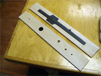
Apply 0.007” CF to inside of root ribs shaped as per photo, using 30-minute epoxy, clamp to flat surface and allow epoxy to cure. Cut holes in CF to match those in ribs. Trim the ribs to root airfoil, leaving a little excess. Epoxy ½” thick x 5/8” wide balsa doublers vertically across the ribs at the adjuster socket locations. Epoxy 5/8” square x 1/8” lite ply “washers” at the wing-bolt holes. Center drill the four provided wing bolt ply plates 5/16”. Trim the fuse interior glass to the outline of the ply plates at each bolt location. Install a ¼” - 20 x 1” nylon hex head capscrew at each of the four rib locations using epoxy (Hysol) to fasten. Apply masking tape to the inner end of the adjuster sockets and epoxy (Hysol) into the ribs / doublers. Epoxy (Hysol) each wing bolt ply plate inside the fuse. Attach the root ribs to the fuse with the nylon bolts and wing nuts. Allow the epoxy to cure.
 |
 |
Remove foam from the wing panel roots to accommodate the wing bolt heads and adjuster socket support. Trim adjuster socket doublers to fit inside the wing skins. Attach the root ribs using Probond, ensuring that the centerlines on ribs and wing panels match. Allow to cure overnight. Apply 2” wide masking tape to wing skins for protection and sand root ribs to match skins. Cut the wing tube sockets flush with ribs and, likewise, cut the fuse wing tube socket flush with the fuselage sides. Remove the adjusters from fuse, install the wing tube and one wing panel with attachment wing nuts loose. With the wing vertical, work a strip of 220 sandpaper between the wing and fuse. Adjust tension of wing nuts to allow efficient material removal and sand the root rib to match the fuselage contour. Repeat for the other wing. Install an adjuster “frame” to the outside of the fuse with mounting screws. Grind the fuse and ply plates to the slot shape of the adjuster frame. Reinstall the wing adjusters.
Final Alignment
Vertically elongate the wing bolt holes in the fuse approximately 1/8”. Install the fuse in the fuselage jig, install wing and stab panels, and position Vee blocks and supports. Ensure the fin is vertical and the fuse is level (basis the wing reference dots / canopy flange). Verify 0 degrees wing incidence, adjust with the wing adjusters if necessary. Double check for perpendicularity. Likewise, verify 0 degrees stab incidence and adjust with the stab adjusters as necessary, tightening the stab adjusters. Move only the bottom stab adjuster screws for subsequent disassembly / assembly to maintain stab alignment. Double check for perpendicularity with fin and parallel to wing. (Any major errors are hard to fix at this point, but there is great satisfaction in knowing that all is well!) Remove assembly from the Vee blocks and jig. Give it one final visual for alignment. (If it looks right it probably is.)
 |
 |
 |
Tailwheel
The fuse is molded to
accept a MK tailwheel assembly. I found the wheel itself to be unacceptable,
however replacement with a ¾” diameter Du-Bro wheel works well. A #2 washer
is soldered to the axle as a retainer, as the thicker wheel precludes using a
steel collar. Replace the spring washer that retains the strut assembly in the
mount with a small wheel collar for security. Notch the strut where the setscrew
seats and Loctite the screw.
Mark the tailwheel flat on the sub-fin for mounting bolt holes and a clearance hole for the strut collar. Drill the mounting hole locations #33 and the strut location ¼”. Fit a piece of ¼” 5-ply plywood to the interior of the sub-fin to anchor the tailwheel assembly, leave room for the fin post. Shape the ply to fit the rounded fuse area and mark to match the holes in the fuse. Drill #25 for mount bolts and 5/15” to clear post / collar. Install 4-40 blind nuts with epoxy. Drill lightening holes to minimize material mass. Install the plywood with epoxy (Hysol) and install the tailwheel assembly with 4-40 mounting screws. Allow epoxy to cure.
Elevator Servos
Cut the bottom of the stab panels to accept your choice of elevator servos. Ensure that they are mounted perpendicular to the stab tube. The inner front point is 2” behind the LE and 1” from the root. Cut and remove the skin for the opening and use a hot wire (1/16 wire bent to shape and mounted in a soldering gun) to remove the foam. Determine the rail positions to place the servo case top flush with the surface. Slot the foam ¼” deep and ¼” beyond the servo cutout. Epoxy (Hysol) 1/8” lite ply rails into the slots. Use a sharpened brass tube to cut a servo lead passage through the root rib and foam. Establish the servo lead holes on the fuse, then cut the appropriate holes in the fuse. Install the servos and drill the rails for mounting screws.
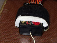
Rudder Servo Tray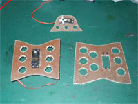
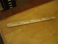
The supplied
Nome x rudder servo tray is cut to fit the rudder servo, lightening holes cut,
and 3/32” ply strips added at each end of the servo cutout for mounting
integrity. For a high load servo application I prefer to use #2-56 blind nuts
and 2-56 x ½” socket head capscrews for mounting.
(The other trays in the photo include an unused elevator
tray and the throttle servo tray in the background.)
x rudder servo tray is cut to fit the rudder servo, lightening holes cut,
and 3/32” ply strips added at each end of the servo cutout for mounting
integrity. For a high load servo application I prefer to use #2-56 blind nuts
and 2-56 x ½” socket head capscrews for mounting.
(The other trays in the photo include an unused elevator
tray and the throttle servo tray in the background.) 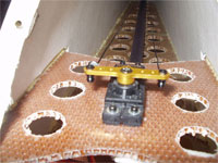 The rudder servo tray is
install behind the canopy with the top of the tray in the same plane as the
canopy flange. Remove the fiberglass / foam where the tray mounts and install
with Probond.
The rudder servo tray is
install behind the canopy with the top of the tray in the same plane as the
canopy flange. Remove the fiberglass / foam where the tray mounts and install
with Probond.
Wing / Stab / Rudder Facings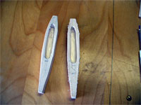
Install the LE – TE balsa to the wing, stab, and rudder panels using Probond sparingly. Cut the wing and stab tips to top view and airfoil. (Note: The wing tips consist of 2 balsa blocks glued together.) Remove excess material from inside the tips. Attach the tips with Probond. Cut the elevator / stab for rudder clearance of 45 degrees each direction and face with balsa provided. Protect the skins with 2” masking tape and shape the facings and tips to the skin. Draw a centerline on the LE and tips.
Hinge Style
The hinges may be either conventionally center hinged, or the more esthetically pleasing top hinged. One consideration is that the thick airfoil section at the hinge positions dictates thicker (therefore heavier) wood and larger surface gaps on both sides of the hinge for center hinges. I chose to top hinge, however other issues surfaced. The hinge insertion point is just below the surface skin. Great care must be exercised to avoid surface “bumps” from the hinges raising the skin (of course the surfaces are covered at this point, so there is no easy fix.) The other observation is that the hinges / wood doesn’t absorb as much CA. This may be caused from some of the hinge being in contact with the skin, which is already coated with epoxy. Actually, as the facing balsa at the hinge insertion point is ¼” thick, the answer may be to trim the hinges so that they don’t protrude through the facing. (I’ve found through testing and use that the Radio South Pro Hinges are the hinges of choice. I prefer the wide “1/4 Scale” version.)
Hinge Lines
PLProd accurately marks the surfaces for the hinge lines. The provided 6mm-balsa facing is sized for installation before the tips and is too short if tips are installed first. I prefer to install the tips and shape as one piece before cutting the hinge lines. Also it’s easier to cut the bevels without having to cut across grain on the tips. Simply replace the facings with 5# density ¼” balsa of sufficient length. Allow for the facing thickness on each side of hinge center and clearly mark. I use a bandsaw with a thin ½’ wide blade to make the cuts. Tape the panels to the appropriate wing shuck for cutting to ensure that the cuts are perpendicular to the chord centerline. PL refers to a reinforcement at the inner end of the aileron cutout. Simply cut a wing side facing slot 1 ½” past the aileron inner end. Reinforce the ¼” facing with a 1” x 3” strip of 0.007 CF epoxied (30-min.) to the front of the facing centered on the aileron end.
Control Horn Reinforcement
Determine the location of the control horns on the ailerons, elevators and rudder. (The rudder horns are placed at the level of the rudder servo arm.) Remove foam from between aileron / elevator / rudder skins at horn locations to accept 1 ½” triangles of balsa. Trim soft balsa triangles to fit between skins and Probond in place. Trim to the edge after glue cures and attach the facings using Probond. Again protecting skin with tape, trim hinge facings to skin.
Mark the apex of the aileron / stab hinge lines 2mm below the surface of the upper skin. Mark the stabs / elevators for a 15-degree bevel each, above and below the hinge line. Likewise mark the wings / ailerons for a 9-degree bevel each. The rudder facing receives a centerline and bevel of 45 degrees (22 ½ each side). Apply masking tape to the top and bottom bevel lines as reference and cut / sand bevels. (The rudder post and fin post are both beveled to allow 45 degrees of rudder travel.)
Rudder Cables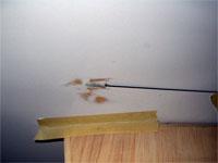
Locate the rudder cable exit holes on the fuse by drawing a line on the fuse between the rudder horn and servo arm elevation. Average the length of the servo arm and rudder horns (overall). Set a caliper to this dimension and find this fuselage width on the cable line. Drill a 1/8” hole through both sides of the fuse and elongate to accept 1/8” OD plastic tubing in the plane of the cables. Roughen 2” pieces of tubing and apply epoxy (Hysol) to the tubing and fuse hole area. Insert the tubing and align by placing a piece of 3/32” music wire through the tubing and extending from the rudder horn to the servo arm. Build a smooth fairing for the tubing with Hysol on the outside. Epoxy (Hysol) a 1” square of 3-oz glass cloth over the tube on the inside. Allow epoxy to cure. Remove the music wire and trim the tubing so that it protrudes from the fuselage by the OD at the rear.
Fin Post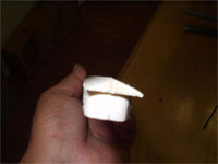
The provided fin post fits nicely. However, inserting the fin post in the normal manner will leave the Kevlar edges of the fin surrounding the post. These edges are difficult to finish. Additionally, a 90-degree bevel on the rudderpost requires a thicker post than provided to maintain integrity. My approach is to apply a ¼” balsa “cap” to the rear of the fin post. (Overall fuse length will still be < 2-meters.) This “cap” covers the Kevlar fin edges and is finished to the shape of the fin after installation. Additionally, the ¼” “cap” receives a 45 degree bevel (22 ½ each side) to match another 45 degrees on the rudderpost. The double bevel is more esthetically pleasing also. After determining the rudder hinge locations, excess material is routed from the hinge post for lightness. Install the fin post with epoxy (Hysol). When the epoxy is cured trim the “cap” to the fuse surface and apply a layer of 0.6-oz./ yard glass cloth with finishing resin. Absorb excess resin by rolling with a roll of toilet tissue. Trim when cured, sand lightly, and apply another thin coat of finishing resin. Wet sand smooth with 320 wet-dry.
Hinge Slots
Mark the hinge
locations. Good practice requires a hinge within an inch of the ends of a
control surface and another near the control horn. Another evenly spaced between
each of the first three provides a reliable hinge of five elements.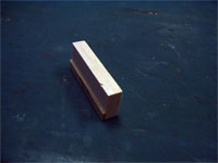
It is imperative that the hinges (except for rudder) are all installed equidistant from the top surface and parallel to the wing skin. (Mismatches in height will look terrible and improper angle can result in the hinge protruding through the skin.) Fabricate a jig from a piece of 3/8” x 1” x 3” balsa to which is attached a ¼” x 2mm piece of plywood. Mark the hinge width on the jig for a reference. To use, place the balsa portion flat on the top wing skin, with the ply against the hinge face. Use the ply face (parallel to the wing skin) to guide a #11 Xacto blade. Carefully cut the hinge slots.
Install the hinges (without glue) and align the control surface with the tip of each component. Shim aileron hinge lines, to establish a 1/64” gap, and trim TE to match wing. Trim inboard end of aileron to provide clearance to wing and face aileron and wing with 1/16” balsa. Cut rudder hinge slots on the centerline and temporarily install the hinges. Shape the top of the rudder to match fin and bottom to match sub-fin.
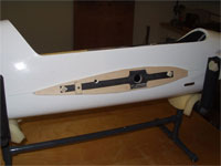
Fuselage Openings
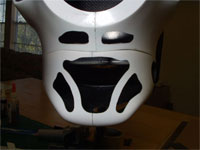
Carefully cut the vent holes in the fuselage and cowl. The arrangement of these is somewhat arbitrary and there are several examples in the photos at PLPROD.com
Mark with a Sharpie and work carefully with Dremel grinding stones. Finish with various diameter dowels wrapped with 220 sandpaper. Cut the cowl for exhaust header clearance (YS) and access to the glow plug. Cut a hole in fuse for access to the needle valve. Slot the fuselage at landing gear plate to accept the landing gear.
 |
 |
 |
 |
Landing Gear and Wheel Pants
I use axles similar to the
NMP brand, offered by Central, that I fabricate from aluminum 5/16”rod. The
axle portion is turned to 3/16” and grooved for an e-clip. The “hub”
length is adjusted to accommodate the wheel pant width (¼” for Bolly pant).
The axle length is cut for Dave  Brown 2 ½” wheels. The axle is drilled to
accept a 1”x #6-32 socket head capscrew. Other axles will work and the
installation methods are similar.
Brown 2 ½” wheels. The axle is drilled to
accept a 1”x #6-32 socket head capscrew. Other axles will work and the
installation methods are similar.
Bolly wheel pants are fitted with 3/32” x ½” x 7/8” light weight aluminum plates epoxied (Hysol) at the axle / anti-rotation pin location.

Install the landing gear struts. Prop the fuselage up to level (canopy flange). Verify that the fin is vertical. Trim gear bottom if necessary to correct fin vertical alignment. Remove the gear and drill the landing gear axle / pant mounts on a vertical centerline, 5/16” up from the bottom #28, and 7/16” up from the bottom #33. Re-install the gear struts and prop-up the struts up ¼” on each side. Place the wheel pants in position and ensure that they are flat on the bench. Mark the axle hole on the pants. Drill the axle holes #28 and assemble the strut, pant, and axle. Verify alignment and mark the pin holes on the pant. Drill the pant #43 and tap the aluminum plate 4-40. Assemble the wheel pants, wheels (2 ½ to 3” Dave Brown) and axles, to the struts with a 6-32 axle capscrew with washer and a 4-40 anti-rotation screw.
Install a ¼” x ¾” dowel in the rudder bottom for the steering pin. Place the dowel so that the pin doesn’t bind in the slot of the rudder tiller. Center drill the dowel #70 for the provided pin, but don’t install the pin until final assembly.
Control Horns and Linkage
Install the elevator servos. Install aileron servo mounting plates and servos. Install servo arms, perpendicular to fuse center, and establish a line to the control surface that’s perpendicular to the servo arm at the point of linkage attachment. Mark the horn location on the control surface. I prefer MK control horns (medium on ailerons and short on the elevators and rudder) as they’ve demonstrated the ability to withstand the loads involved. These are affixed to ½” diameter dowels inserted into the control surface. Apply masking tape to the top skin and place on a clean lite ply surface (to prevent tear-out). Bore a ½” diameter hole, centered on the mark span-wise, with the front just on the edge of the hinge bevel, and perpendicular to the top surface. (This will tilt the horn toward the hinge center. Cut ½” poplar dowel pieces that are perfectly square on one end and slightly longer than the surface thickness. (The rudder dowel is squared on both ends and sized to thickness of the TE of the hole.)
There are different methods by which to fasten the aileron and elevator horns to the dowels. The dowels may be center drilled #32 for though bolt clearance and countersunk (#3 drill) on top to recess the head of a 3mm socket head capscrew. This method is bullet proof but a little heavy. I chose to center drill the dowel #40 about 7/8 the way through and tap 3mm x 0.5. The horn is attached using the MK provided screws with the head removed. Epoxy or CA used in the final assembly makes this sufficient. (The rudder is attached with a threaded rod, made by cutting from a 3mm capscrew, protruding from each side of the dowel.)
After the
dowels are prepared, epoxy (30 min.) each into their control surface so that the
square end (perpendicular to hole) is to the bottom of the surface and flush
with the skin at the TE side of the hole. Trim the top of the dowel even with
the top skin using a Dremel router set flush and a sanding block.
Temporarily install the horns and linkage. I used MK 2.5mm (red) ball bearing clevises and rod ends with Hangar 9 Titanium 4-40 pushrods. Replace the screws provided with the MK hardware with socket head capscrews and use nuts to lock screws in servo arms and clevises.
Miscellaneous Component Mounting and CG
PL instructions call for
the CG to be 24mm behind the center of the wing tube. It’s prudent to ensure
that the CG will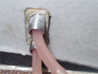 be close to that spec with normal equipment locations before
proceeding to the finishing (Which will move the CG rearward some amount.)
be close to that spec with normal equipment locations before
proceeding to the finishing (Which will move the CG rearward some amount.)
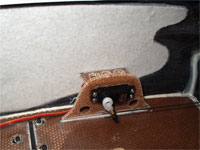
Select a position forward of the wing LE on the right fuse side and bore holes to accept fuel dot sockets. Cut a 1/8” lite ply plate to surround the dots and mark around the plate positioned over the dot holes. Remove the glass / foam from the marked area, insert the ply plate, and mark the dot socket holes on the plate. Drill the plate 3/8” and epoxy the plate to the fuselage.
 Temporarily install the
fuel tank with all lines and fittings. Install
all radio components, including servo leads but excluding
the battery pack.
Mount the receiver on the fuse floor below the rudder servo to minimize the
elevator servo lead extension lengths. Slot the honeycomb floor through one side
and through the Nomex each side of the receiver so as to fit a Velcro strap.
Probond Velcro strapping into each slot. Use ¼” double sided foam tape under
the receiver and a foam strip between the receiver and the Velcro strap to
retain the receiver.
Temporarily install the
fuel tank with all lines and fittings. Install
all radio components, including servo leads but excluding
the battery pack.
Mount the receiver on the fuse floor below the rudder servo to minimize the
elevator servo lead extension lengths. Slot the honeycomb floor through one side
and through the Nomex each side of the receiver so as to fit a Velcro strap.
Probond Velcro strapping into each slot. Use ¼” double sided foam tape under
the receiver and a foam strip between the receiver and the Velcro strap to
retain the receiver.
 (Use a vacuum cleaner to
draw a string through the elevator cable conduit to install the elevator servo
leads.) Mount the voltage regulator (Perfect Switch) to the bottom of the rudder
servo tray near the left fuse side with double-sided foam tape. Glue (Probond)
sections of Gator Featherlite tubing under the canopy flange on each side to
route servo and power leads. Using
the switch and charge socket bezels as guides, cut and drill the fuselage. Mount
the switch and charge socket with a 1/8” lite ply plate in the fuse.
The battery pack and throttle servo are items used to finalize the CG
location. Assemble the remainder of the airplane and determine the CG.
(Use a vacuum cleaner to
draw a string through the elevator cable conduit to install the elevator servo
leads.) Mount the voltage regulator (Perfect Switch) to the bottom of the rudder
servo tray near the left fuse side with double-sided foam tape. Glue (Probond)
sections of Gator Featherlite tubing under the canopy flange on each side to
route servo and power leads. Using
the switch and charge socket bezels as guides, cut and drill the fuselage. Mount
the switch and charge socket with a 1/8” lite ply plate in the fuse.
The battery pack and throttle servo are items used to finalize the CG
location. Assemble the remainder of the airplane and determine the CG. 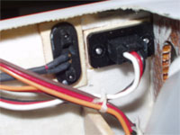
 Assess if
a normal location is practical for the throttle servo (likely). For reference,
I
found that the aircraft balanced at this point with a 5-cell 1650mah NiMH
battery pack placed immediately behind the rear tank bulkhead. This position
changed to just inside the rear tank bulkhead after finishing.
Assess if
a normal location is practical for the throttle servo (likely). For reference,
I
found that the aircraft balanced at this point with a 5-cell 1650mah NiMH
battery pack placed immediately behind the rear tank bulkhead. This position
changed to just inside the rear tank bulkhead after finishing.
Finishing
Completely disassemble the aircraft. Mark right and left components and store for easy re-assembly. Round the wing / stab LE and tips maintaining a consistent radius above and below the centerlines. Finish block sand all wood surfaces with 320 and 400 grit sandpaper.
There are numerous options and method of finishing. It’s beyond the scope of this document to explore each. I chose to use Monokote for the wood surfaces and Radio South Flying Colors for the composite surfaces. My skills with Monokote are limited and I won’t contaminate you with my vagaries.
My observations regarding the composites may be helpful. The gelcoat of the PL fuselages don’t require priming and, depending on your color scheme, may suffice for white areas. Do not attack high spots of the seams with sandpaper, to do so will penetrate into the composite and be difficult to overcome. There will be some air pockets between the gelcoat and composites. These must be opened and filled to prevent flaking (with the paint) later. Inspect the fuselage surface carefully and probe all depressions or suspicious spots and remove loose gelcoat. Mix PPG K-36 Prima, K-201 catalyst, and talc to form a paste. Fill all voids and seam low areas with this material. (Don’t forget the wheel pants.) Wet sand (220), again being careful to not penetrate the gelcoat. Inspect the fuselage surface with a bright light to discover any foreign material deposited during construction, especially adhesives. Carefully remove blemishes with solvent or careful wet sanding.
The Bolly landing gear and wheel pants contain copious pinholes that require attention. BVM Pinhole Filler works best. Apply as per directions. I prefer to remove the excess after it has dried by rubbing with 0000 grade steel wool.
Take the time to construct suitable fixtures to securely hold the parts to be painted. Use proper protection when painting. Full body cover, including eyes, and a remote supply air mask is best.
Wipe everything with PPG DX-330 cleaner. Using an airbrush or spay gun set to a very narrow pattern (Sata Mini-jet III works great.) spray a heavy, narrow coat of primer on the seams, a light coat over any filled spots on the fuse, the entire landing gear, and wheel pants. Wet sand the seam with 400 grit and repeat primer application and sanding until smooth. Lightly wet sand the entire fuselage, gear and pants with 400 grit paper. Again clean with DX-330. Tack all parts to remove dust and paint. Be aware that this fuselage has a large amount of surface area and can gain a great deal of weight if too much paint is used. A gun that atomizes the paint well allows even coverage with less paint. I also find that thinning the PPG / Radio South paints 2X the recommended amount works well.
Final Assembly
Assemble hinged surfaces and glue the hinges in place with extra thin CA. Work on one hinge at a time and ensure good glue absorption and no excess wicking into hinge line. (A couple of 1/64” ply spacers help to establish the proper gap.) Quickly remove any errant CA with debonder. After the CA has cured remove CA “fogging” with debonder. Seal all hinge lines with “BlendermÒ” surgical tape.
Carefully assemble all components into the airframe. Remember to tighten the bottom stab adjuster screws only. Install the stab retaining screws. Tie all radio lead connections, including the connections at the receiver. Use small pieces of foam to prevent chafing of the aileron and elevator servo leads where they exit the wing and stab panels. Use a liquid thread lock on all screws. Use plumber’s Teflon tape on header to engine fitting (YS). Install the tail wheel tiller pin in the rudder with epoxy or CA. Install the rudder cables, crossed to obtain the straightest route between connecting points. Use nylon coated 0.035” Kevcord (Aerospace Composites) for long-term durability.
Fabricate a soft nose ring from 3/16” 60A durometer polyurethane (McMaster-Carr # 8789K322) using a CF Engineering ring as reference. Cut the engine hole with a 1” hole saw that has had the exterior set ground away. Place both rings on an engine and mark the horizontal mount holes. Rotate the CF ring 90 degrees and mark a vertical mount hole. Cut 1/8” holes (brass tubing) at the marks. Cut the Poly nose ring to approximate the shape of the CF ring, with an additional mounting hole. (Sharp knife works well.) Install the nose ring with 4-40 x 3/8” capscrews and 1/8” aluminum step bushings that are 1/8” long and have a ¼” step.
Set the CG 24mm behind the wing tube center by moving the battery pack accordingly. Anchor the battery pack with Velcro straps fastened into the honeycomb floor with Probond. (Mine is under the tank and in front of the rear tank bulkhead.)

Install the fuel tank with 1/8” foam tape around the tank at the bulkheads. Place a 1/8” x ¾” tank restraint across the fuselage at the rear of the tank. Epoxy to fuse sides after removing glass / foam. Install a Velcro strap at the front of the tank and Probond through the bulkhead.
Verify that all controls move the proper direction. Aileron travels of ± 12 degrees, elevator travels of ± 10 degrees, and rudder travels of ± 40 degrees is a good starting point. (The elevator authority is quite good for it’s size.) Take the time to adjust both elevators to be in line with each other and travel exactly the same amount. Use good quality throw meters and get it exact with the radio and linkage adjustments.
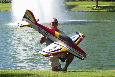
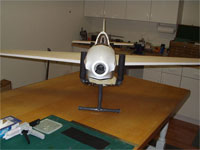
The airplane pictured at the beginning of this document weighs 10.25# dry and flew without surface trim offsets. As of this writing I’ve completed an insufficient number of flights to comment on flight characteristics except to say is feels solid and demonstrates no adverse performance in the typical F3A maneuvers.
I hope that this document is useful and helped make construction of the Partner an enjoyable experience.